![[20FT] EVIL ENERGY PTFE Fuel Line Kit, complete black hose & fittings set, 180-day return](http://www.ievilenergy.com/cdn/shop/files/Test-2025-Evilenergy-125598065_940x.png?v=1742144807)
![[16FT] EVIL ENERGY PTFE Fuel Line Kit, black braided hose, fittings, free shipping & return](http://www.ievilenergy.com/cdn/shop/files/Test-2025-Evilenergy-125598171_940x.png?v=1742144807)
![CPE Fuel Line[25FT]](http://www.ievilenergy.com/cdn/shop/files/25FTCPE_FuelLine_940x.png?v=1735220649)
![CPE Fuel Line[20FT]](http://www.ievilenergy.com/cdn/shop/files/20FTCPE_FuelLine_940x.png?v=1735220649)





Intake Manifold Guide: Plenum, Runners, Single vs Dual Plane, Hi-Ram, EFI, and Carbureted

🎁 A Personal Gift For My Readers
To support your project, I've secured an exclusive 8% OFF for you.
Simply paste the code at checkout.
💡 Use the savings to grab your extra fittings, oil lines, or connectors for free!
An intake manifold is not simply an adapter between the throttle body or carburetor and the cylinder heads. Its plenum, runners, port shape, flange design, injector provisions, and installed height influence airflow distribution, operating range, throttle response, fuel-system layout, and engine-bay clearance.
This guide explains how intake manifolds work, compares dual-plane, single-plane, Hi-Ram, EFI, and carbureted designs, and shows how a professional technician verifies cylinder-head ports, throttle or carburetor fitment, fuel-system components, sealing surfaces, vacuum connections, and hood clearance before installation.
Quick Answer
An intake manifold distributes air—or an air-fuel mixture on many carbureted engines—to the individual cylinders. Select one by confirming the engine family, block and deck geometry, cylinder-head port style, manifold bolt and sealing pattern, runner and plenum design, intended RPM range, EFI or carbureted layout, throttle-body or carburetor flange, injector and fuel-rail requirements, sensor provisions, vacuum connections, and total installed height.
A manifold that physically sits on the engine is not necessarily compatible. Port alignment, gasket support, throttle or carburetor opening, injector position, fuel-rail clearance, accessory interference, and calibration must also be verified.
Single-plane, dual-plane, and Hi-Ram labels describe manifold architecture. They do not guarantee a specific horsepower increase, torque curve, idle quality, or operating range on every engine.
Key Takeaways
- Cylinder-head port family, block geometry, bolt pattern, and sealing surfaces are nonnegotiable fitment checks.
- Runner length, runner area, plenum volume, and manifold height should match engine displacement, cylinder-head flow, camshaft, gearing, and intended RPM range.
- A dual-plane manifold often supports a broad street operating range, while a single-plane manifold is commonly selected for combinations that prioritize higher-RPM airflow.
- A Hi-Ram intake manifold requires careful hood, cowl, accessory, throttle-body, fuel-rail, and intake-tube clearance planning.
- EFI manifolds may require injectors, fuel rails, pressure regulation, sensors, wiring, throttle control, and calibration that are not included with the manifold.
- Total installed height includes the manifold, gaskets, spacers, adapters, throttle body or carburetor, air cleaner, fuel rails, fittings, and engine movement.
- Intake manifold leaks should be diagnosed with fuel-trim data, smoke testing, vacuum testing, coolant pressure testing, and visual inspection rather than parts replacement alone.
What Does an Intake Manifold Do?
The intake manifold connects the engine’s air-control component to the cylinder-head intake ports. On a port-injected EFI engine, the manifold usually carries air while injectors deliver fuel near each intake port. On many carbureted engines, the manifold distributes an air-fuel mixture from the carburetor to the cylinders.
The intake manifold must perform several functions:
- Distribute airflow or air-fuel mixture among the cylinders.
- Provide a controlled path from the plenum to each cylinder-head port.
- Support the throttle body, carburetor, injectors, fuel rails, sensors, and vacuum connections used by the system.
- Seal against unmetered-air, fuel, oil, or coolant leakage where applicable.
- Fit around the water pump, accessory drive, valley cover, ignition components, fuel lines, hood, and firewall.
The manifold is one section of a complete airflow path. For an overview of the air filter, intake tube, MAF or MAP sensor, throttle body, intake manifold, cylinder heads, and valves, read the car air intake system components guide.
What Do the Plenum and Runners Do?

What Is an Intake Manifold Plenum?
The plenum is the shared chamber that receives airflow from the throttle body or carburetor before feeding the individual runners. Its volume, shape, inlet position, internal dividers, and relationship to the runners influence airflow distribution and how the engine responds across the RPM range.
A larger plenum is not automatically better. Plenum size must be considered with engine displacement, runner dimensions, throttle-body or carburetor size, camshaft, cylinder-head flow, vehicle use, and operating speed.
What Are Intake Manifold Runners?
Runners connect the plenum to the cylinder-head intake ports. Important runner characteristics include:
- Runner length.
- Cross-sectional area.
- Port shape and position.
- Taper.
- Curvature.
- Surface transitions.
- Entry shape at the plenum.
- Alignment with the cylinder-head port.
Longer or smaller runners commonly support air velocity and pressure-wave tuning lower in the operating range. Shorter or larger runners may support higher airflow demand at higher RPM. These are general design tendencies rather than universal performance results.
Why Runner Size Must Match the Engine
A runner that is too small for the engine’s airflow demand may become restrictive at higher RPM. A runner that is unnecessarily large can reduce air velocity and weaken response in the operating range used most often.
Runner selection should therefore be based on the complete combination rather than displacement alone. Cylinder-head port size, valve size, camshaft timing, compression, induction type, exhaust flow, and target RPM all affect the result.
For additional planning information, see the LS, SBC, and BBC cylinder-head runner and chamber-size guide.
What Is the Difference Between Single-Plane, Dual-Plane, and Hi-Ram Intake Manifolds?

| Manifold Design | General Architecture | Common Build Priority | Critical Checks |
|---|---|---|---|
| Dual Plane | Divided plenum separates runner groups and limits how each cylinder communicates with the carburetor or inlet. | Broad street operating range, carburetor signal, part-throttle response, and street drivability. | Carburetor flange, plenum divider, runner alignment, port family, installed height, and gasket sealing. |
| Single Plane | One common open plenum feeds all runners more directly. | Higher-RPM airflow in an engine combination designed to use the additional plenum communication and runner area. | Plenum volume, runner size, cylinder heads, camshaft, compression, gearing, converter, and intended RPM range. |
| Hi-Ram | Elevated plenum and runner arrangement designed around substantial airflow demand and a tall installed package. | High-flow combinations where engine-bay packaging and upper-RPM operation have been planned together. | Hood or cowl clearance, throttle-body layout, fuel rails, injectors, fittings, accessories, intake tube, and tuning. |
| EFI-Specific | Includes or supports injector bungs, fuel rails, sensors, vacuum ports, and a throttle-body inlet. | Electronic fuel injection with matched injectors, fuel pressure, sensors, wiring, ECU, and calibration. | Injector style and height, rail spacing, regulator strategy, MAP/IAT provisions, throttle flange, harness, and tune. |
| Carbureted | Supports a carburetor flange and distributes an air-fuel mixture below the carburetor. | Mechanical or electronically controlled carburetor systems with suitable fuel pressure and linkage. | Square-bore or spread-bore flange, linkage, choke, fuel inlet, distributor clearance, spacer, and air cleaner. |
These categories describe architecture, not guaranteed results. A well-matched dual-plane manifold may outperform a poorly matched single-plane manifold in the RPM range the vehicle actually uses. Likewise, a Hi-Ram design can create packaging and drivability problems when the rest of the engine and vehicle are not built around it.
When Is a Dual-Plane Intake Manifold Appropriate?
A dual-plane intake is commonly considered for street-focused carbureted builds that prioritize idle quality, part-throttle response, usable low- and mid-range torque, and a broad driving range. The final result still depends on the exact runner design, carburetor, cylinder heads, camshaft, exhaust, vehicle weight, gearing, and calibration.
For a current product example, review the EVIL ENERGY Ford 351W dual-plane carbureted intake manifold 4023. Confirm engine family and complete installed dimensions before ordering.
When Is a Single-Plane Intake Manifold Appropriate?
A single-plane intake is commonly selected for an engine designed to operate at higher RPM with compatible cylinder heads, camshaft, compression, fuel delivery, converter or clutch, and gearing. Installing one on an otherwise mild street combination does not guarantee an improvement in normal driving conditions.
The EVIL ENERGY 300-131 single-plane LS carbureted intake manifold is currently identified for LS3/L92/L99/L76-style rectangular-port applications. It should not be treated as a universal LS manifold.
When Is a Hi-Ram Intake Manifold Appropriate?
A Hi-Ram intake manifold is intended for combinations where high airflow demand and upper-engine packaging have been planned together. It may require a modified hood, cowl hood, relocated components, custom intake tubing, different throttle-body placement, revised fuel lines, and ECU calibration.
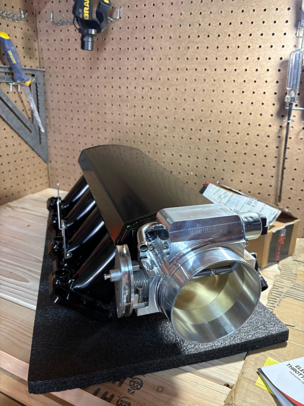
The current EVIL ENERGY 1918S LS3-style EFI Hi-Ram intake manifold is listed for LS3/L92/L99/L76 rectangular-port applications and includes EFI fuel rails. Verify injector, fitting, throttle-body, sensor, hood, and accessory requirements separately.
How Do EFI and Carbureted Intake Manifolds Differ?
| Fitment Area | Carbureted Manifold | Port-Injection EFI Manifold |
|---|---|---|
| Fuel delivery | Fuel is introduced through the carburetor before entering the manifold. | Injectors commonly deliver fuel near the cylinder-head intake ports. |
| Air-control component | Carburetor with mechanical or electronic controls. | Mechanical or drive-by-wire throttle body. |
| Fuel pressure | Requires a pressure range suitable for the selected carburetor. | Requires EFI pressure, injectors, rails, regulator strategy, and pump capacity matched to the system. |
| Electrical requirements | May require electric choke, ignition inputs, or electronic carburetor controls. | Requires ECU, injector wiring, sensors, throttle control, and calibration. |
| Common hardware | Carburetor studs, gasket, linkage, return springs, fuel line, spacer, and air cleaner. | Injectors, O-rings, fuel rails, brackets, fittings, throttle body, sensors, harness, and fuel-pressure components. |
| Primary installation risk | Incorrect flange, linkage binding, excessive fuel pressure, vacuum leaks, or insufficient hood clearance. | Injector or rail mismatch, connector incompatibility, fuel leaks, sensor errors, throttle-control mismatch, or incomplete calibration. |
What Must Be Checked Before Buying an EFI Intake Manifold?
- Injector length, diameter, connector type, flow rate, and O-ring size.
- Fuel-rail spacing, mounting points, bore size, and fitting thread.
- Return-style or returnless fuel-pressure strategy.
- Fuel-pump capacity and compatible fuel type.
- Throttle-body bore, flange, control type, and connector.
- MAP, IAT, brake-booster, PCV, fuel-pressure-reference, and other vacuum provisions.
- ECU, wiring harness, injector drivers, and calibration support.
- Whether gaskets, rails, injectors, brackets, fittings, sensors, and hardware are included.
For throttle-body control type, bore selection, connector checks, and LS compatibility, read the throttle body DBW, cable, sizing, cleaning, and LS fitment guide.
Can a Carbureted Manifold Be Converted to EFI?
It may be possible with throttle-body injection, a purpose-built injector conversion, or a manifold designed for retrofit hardware. However, adding a throttle body or injector bungs does not by itself create a complete EFI system.
The conversion must account for injector placement, rail mounting, fuel pressure, pump capacity, regulator strategy, sensors, wiring, ECU control, ignition strategy, throttle linkage or DBW control, and tuning. Improvised fuel-system components can create fire and drivability risks.
How Do You Choose the Right Intake Manifold?
Start with the engine and vehicle requirements, not the advertised manifold type.
1. Confirm the Exact Engine Family
Identify the block family, deck height, cylinder heads, intake-port style, model year, displacement, and any mixed-generation components. An engine name alone may not identify the installed heads or intake pattern after previous modifications.
2. Define the Actual Operating Range
Consider where the engine spends most of its time:
- Idle and low-speed street use.
- Daily driving and highway cruising.
- Towing or truck use.
- Street and strip use.
- Road-course operation.
- Drag racing.
- High-RPM naturally aspirated use.
- Supercharged or turbocharged operation.
The useful operating range should be matched with the camshaft, cylinder heads, exhaust, torque converter or clutch, transmission ratios, axle ratio, tire size, and vehicle weight.
3. Match the Cylinder-Head Ports
Verify port family, port height, width, shape, bolt pattern, sealing-bead location, and manifold alignment. Do not assume that similar engine-family names use the same intake port.
4. Match the Fuel and Throttle System
Confirm whether the build uses a carburetor, throttle-body injection, port EFI, mechanical throttle, or drive-by-wire control. Check every required component rather than focusing only on the manifold casting.
5. Check Installed Height and Surrounding Clearance
Measure the complete installed stack, including:
- Intake manifold.
- Manifold and throttle-body or carburetor gaskets.
- Adapters and spacers.
- Carburetor or throttle body.
- Air-cleaner base, filter, and lid.
- Fuel rails, injectors, regulators, and fittings.
- Throttle linkage, cable bracket, or DBW actuator.
- Vacuum fittings and sensors.
- Intake tube and coupler.
6. Identify the Existing Restriction
A new manifold is most useful when the existing manifold is incompatible, damaged, leaking, or has been identified as a restriction in the intended operating range. It cannot correct undersized fuel delivery, an unsuitable camshaft, restrictive cylinder heads, an incorrect throttle body, or poor calibration.
Use the air filter, cold air intake, throttle body, manifold, and cylinder-head upgrade guide to decide which part of the airflow path should be addressed first.
What Makes an LS Intake Manifold Compatible?

'LS compatible' does not confirm complete fitment. LS-based projects frequently combine blocks, cylinder heads, valley covers, accessory drives, water pumps, throttle bodies, wiring harnesses, ECUs, injectors, and fuel systems from different applications.
LS Intake Manifold Fitment Checklist
- Cylinder-head port family: Confirm cathedral, rectangular, LS7-style, or another specific port arrangement.
- Port position and gasket: Verify port height, width, shape, bolt pattern, and sealing-bead support.
- Throttle-body flange: Confirm bore, bolt pattern, throttle-plate clearance, DBW or cable control, connector, and inlet orientation.
- Injector compatibility: Check injector length, O-ring size, connector, flow rate, and installed angle.
- Fuel rails: Verify spacing, brackets, fitting thread, regulator strategy, and clearance from the coil packs, throttle linkage, and fittings.
- MAP and IAT sensors: Confirm sensor type, mounting style, connector, location, and ECU compatibility.
- Vacuum and PCV provisions: Identify brake-booster, crankcase ventilation, fuel-pressure-reference, purge, and accessory ports.
- Valley-cover and oil-pressure-sender clearance: Check the components actually installed on the engine.
- Water-pump and accessory clearance: Verify front-drive spacing, tensioner, alternator, hoses, and throttle-body position.
- Hood and firewall clearance: Include fuel rails, fittings, intake tube, throttle motor, and engine movement.
- ECU calibration: Injector data, MAP scaling, airflow modeling, idle control, DBW settings, and fueling may require adjustment.
Cathedral-Port vs Rectangular-Port LS Manifolds
Cathedral-port and rectangular-port intake manifolds should not be mixed solely because the bolt holes appear close. Port shape, height, sealing location, runner alignment, and gasket support must be compatible.
A purpose-built adapter or conversion system may solve a specific mechanical interface, but it does not automatically correct port transition, injector position, fuel-rail alignment, hood clearance, sensor compatibility, or tuning.
Before ordering, review the LS cathedral-port and rectangular-port intake compatibility guide.
Will a 351W Intake Manifold Fit a Ford 302?
A standard Ford 351W intake manifold should not be treated as a direct-fit Ford 302 or 5.0L manifold. Although both belong to the Windsor small-block family, their block deck geometry changes the distance and angle between the cylinder-head intake surfaces.
A purpose-built conversion may use special spacers or other matched components, but that does not make an ordinary 351W manifold directly interchangeable with a 302 manifold.
EVIL ENERGY 4023 Product Example
The current EVIL ENERGY part 4023 intake manifold is identified as a dual-plane carbureted manifold for the Ford 351W 5.8L engine family. It should not be ordered as a Ford 302/5.0L, 351C, or 351M/400 manifold.
The product listing gives a manifold operating range of 1,500–6,500 RPM and dimensions of 21.12 × 11.08 × 5.76 inches. These figures describe that product only and do not represent the complete installed height.
Before installation, also verify:
- Actual cylinder-head intake-port and bolt pattern.
- Carburetor flange and throttle-opening clearance.
- Distributor and thermostat-housing clearance.
- Coolant-passage and gasket compatibility.
- Throttle linkage and cable-bracket geometry.
- Fuel inlet and fuel-pressure requirements.
- Carburetor spacer and air-cleaner height.
- Hood clearance and engine movement.
How Do You Check Intake Manifold Hood Clearance?
Manifold height alone is not enough. The complete installed stack must be measured at the engine angle used in the vehicle.
Professional Hood-Clearance Check
- Park the vehicle on a level surface and secure it.
- Establish a repeatable reference from the block, carburetor pad, throttle-body flange, or existing air-cleaner assembly.
- Add the manifold, gasket, spacer, adapter, throttle body or carburetor, air-cleaner base, filter, and lid dimensions.
- Include fuel rails, injector connectors, AN fittings, throttle linkage, DBW motor, vacuum fittings, and intake tubing.
- Place modeling clay or loosely formed aluminum foil on the highest safe point of the assembly.
- Lower the hood slowly without slamming or forcing it.
- Reopen the hood and measure the compressed material to estimate clearance.
- Repeat the check at multiple locations because hood bracing and engine angle can change the available space.
- Allow additional clearance for engine movement under acceleration, braking, and drivetrain load.
Do not start the engine with measuring material, loose tools, uncovered intake openings, or unsecured components in the engine bay.
Do Intake Manifold Ports Need to Match the Cylinder Heads?
Yes. The manifold and cylinder-head ports must use a compatible port family, bolt pattern, sealing arrangement, and physical location. However, 'port matching' should not mean enlarging every port to the outer edge of a gasket without measurements.
What to Check During a Dry Fit
- Port height, width, shape, and vertical position.
- Manifold bolt alignment without forcing the casting.
- Gasket sealing-bead support around the complete port.
- End-seal or valley-wall gaps where applicable.
- Coolant-passage alignment on engines that route coolant through the intake manifold.
- Injector targeting and rail alignment on EFI systems.
- Throttle plate, carburetor blade, or adapter clearance.
- Distributor, water neck, valley cover, and accessory clearance.
Why Gasket Matching Can Cause Problems
The gasket opening may be larger than the cylinder-head or manifold port and may be designed to support more than one application. Grinding both components to the gasket edge can remove sealing area, create a poor transition, weaken the casting, expose a coolant or bolt passage, or make future alignment difficult.
Port work should be based on measured geometry and the intended airflow combination. Protect the engine from metal debris and have substantial modifications completed by an experienced engine machinist or cylinder-head specialist.
Professional Intake Manifold Installation Checklist
Before Removing the Old Manifold
- Record hose, wiring, linkage, sensor, and fuel-line routing.
- Relieve fuel-system pressure according to the applicable service procedure.
- Disconnect the battery when required.
- Drain coolant to the specified level if the manifold contains or intersects coolant passages.
- Clean loose debris from around the manifold before opening the engine.
- Label vacuum hoses and electrical connectors.
- Prevent fuel, dirt, gasket material, and hardware from entering the intake ports or engine valley.
Inspect the Replacement Manifold
- Compare engine family, ports, bolt holes, flanges, and installed height.
- Inspect the casting for shipping damage, cracks, porosity, damaged threads, or debris.
- Confirm all vacuum, sensor, coolant, PCV, and accessory ports.
- Verify throttle-body or carburetor opening and gasket support.
- Check fuel-rail, injector, and fitting clearance.
- Dry-fit the manifold before applying sealant.
Prepare the Sealing Surfaces
Remove old gasket material without gouging aluminum surfaces or allowing debris into the engine. Inspect the cylinder-head and manifold sealing surfaces for corrosion, damage, warpage, or previous over-tightening.
Use the gasket type and sealant placement specified for the engine and manifold. Do not apply RTV around every port unless the manufacturer specifically requires it. Excess sealant can squeeze into the intake, oil, or coolant passages.
Install the Manifold
- Position the gaskets and required end seals or sealant.
- Lower the manifold into place without sliding it excessively across wet sealant.
- Start every fastener by hand.
- Verify that the manifold sits naturally without using bolts to pull a misaligned casting into position.
- Follow the engine- and manifold-specific tightening sequence.
- Tighten in stages using a calibrated torque wrench.
- Do not use a generic torque value for different fastener sizes, cylinder-head materials, or manifold designs.
- Retorque only when the manufacturer or gasket procedure requires it.
Install EFI Components
- Inspect and replace damaged injector O-rings.
- Lubricate O-rings only with an approved lubricant.
- Insert injectors and rails squarely without cutting or rolling the seals.
- Support fuel rails evenly before tightening the brackets.
- Verify fitting thread type before installing AN, ORB, or NPT adapters.
- Pressure-test the fuel system with the engine off before starting.
- Correct every fuel leak before operating the engine.
Install the Throttle Body or Carburetor
- Use the correct flange gasket.
- Check throttle-plate or carburetor-blade clearance.
- Verify cable alignment, full travel, return-spring operation, and linkage clearance.
- For DBW systems, confirm throttle body, pedal, ECU, harness, and calibration compatibility.
- Make sure fuel fittings and linkage do not contact the manifold, distributor, air cleaner, or hood.
Before the First Start
- Reconnect every vacuum, PCV, coolant, sensor, fuel, and electrical connection.
- Remove all port plugs, rags, tape, and tools used during installation.
- Refill and bleed the cooling system when applicable.
- Prime and pressure-test the fuel system.
- Check for fuel and coolant leaks with the engine off.
- Start the engine and monitor oil pressure, coolant temperature, fuel pressure, idle quality, and diagnostic codes.
- Inspect for vacuum, fuel, coolant, and oil leaks.
- Perform required throttle, idle, injector, MAP, or ECU calibration procedures.
What Causes Intake Manifold Leaks?
An intake manifold can leak air, fuel, coolant, or oil depending on the engine design and failure location.
| Leak Type | Possible Symptoms | Professional Checks |
|---|---|---|
| Vacuum or unmetered-air leak | High or unstable idle, lean fuel trims, lean codes, hesitation, misfire, whistle, or poor brake-booster operation. | Scan fuel trims, inspect hoses and ports, perform a controlled smoke test, and check manifold and throttle-body gaskets. |
| External coolant leak | Coolant odor, visible wetness, low coolant level, staining, or overheating. | Cooling-system pressure test, visual inspection, and verification of coolant-passage gasket alignment. |
| Internal coolant leak | Coolant loss without an obvious external leak, contaminated oil, exhaust vapor, misfire, or overheating. | Cooling-system pressure test, oil and coolant inspection, cylinder testing, and engine-specific diagnosis. |
| Fuel leak on EFI hardware | Fuel odor, wet injector or rail area, pressure loss, hard start, or fire risk. | Key-on pressure test, injector O-ring inspection, rail alignment, fitting verification, and fuel-pressure monitoring. |
| Carburetor or flange leak | Unstable idle, lean mixture, hesitation, poor carburetor signal, or fuel staining. | Inspect flange flatness, gasket selection, carburetor torque, spacer alignment, linkage, and vacuum ports. |
Common Causes of Intake Manifold Leaks
- Incorrect or damaged gaskets.
- Wrong port-family gasket.
- Damaged, dirty, corroded, or warped sealing surfaces.
- Improper sealant type or placement.
- Excessive sealant preventing correct seating.
- Uneven tightening or incorrect torque sequence.
- Fasteners bottoming in blind holes.
- Manifold and cylinder-head geometry that does not align.
- Loose or uncapped vacuum ports.
- Cracked PCV, brake-booster, purge, or MAP hoses.
- Damaged injector O-rings or misaligned fuel rails.
- Cracked or porous castings.
Why a Smoke Test Is Useful
A controlled low-pressure smoke test can help locate air leakage at manifold gaskets, throttle-body flanges, vacuum fittings, injector seals, PCV connections, and hoses. Use equipment and pressure appropriate for the system.
Avoid using flammable spray as the primary diagnostic method around hot engines, ignition sources, alternators, or exposed wiring.
How Does the Intake Manifold Match the Complete Engine Combination?
The intake manifold should be selected with the cylinder heads, throttle body or carburetor, camshaft, exhaust system, fuel delivery, transmission, gearing, vehicle weight, and ECU calibration.
A manifold cannot be evaluated only by peak airflow or advertised RPM range. The vehicle must also start, idle, transition through part throttle, maintain fuel distribution, clear the hood, and operate within the intended street or track conditions.
Questions to Answer Before Ordering
- What exact engine block and cylinder heads are installed?
- What intake-port family, shape, and bolt pattern are used?
- What RPM range will the engine actually operate in?
- Is the vehicle street-driven, used for towing, or built primarily for racing?
- What camshaft, compression ratio, exhaust system, transmission, converter, and gearing are installed?
- Does the build use a carburetor, port EFI, throttle-body injection, or another fuel strategy?
- Which throttle body or carburetor flange is required?
- Are injectors, fuel rails, fittings, sensors, gaskets, and hardware included?
- Will the complete assembly clear the hood, accessories, firewall, and intake tube?
- Is compatible ECU calibration or carburetor tuning available?
- Has the existing manifold been identified as the restriction or failure point?
For a complete top-end planning process, read the guide to matching cylinder heads, intake manifold, throttle body, and camshaft.
Who Is This Guide For?
This guide is intended for carbureted engine builders, EFI converters, LS Swap owners, classic-car restorers, street-performance users, and DIY project planners comparing intake manifold designs or diagnosing manifold fitment and sealing problems.
Frequently Asked Questions
Q: What does an intake manifold do?
A: An intake manifold distributes air—or an air-fuel mixture on many carbureted engines—from the throttle body or carburetor to the individual cylinder-head intake ports.
Q: Is a single-plane intake manifold always better for racing?
A: No. Suitability depends on engine displacement, target RPM, cylinder heads, camshaft, compression, fuel system, exhaust, converter or clutch, gearing, vehicle weight, and the exact manifold design.
Q: Is a dual-plane intake manifold better for street use?
A: A dual-plane manifold is commonly selected for a broad street operating range and carburetor signal, but the result depends on the complete engine and vehicle combination.
Q: Does a larger intake manifold plenum make more power?
A: Not automatically. Plenum volume must match engine displacement, airflow demand, runner design, cylinder heads, camshaft, throttle-body or carburetor size, and operating range.
Q: Does a Hi-Ram intake manifold fit under a stock hood?
A: Often not without careful measurement or body modifications. Measure the complete installed stack, including fuel rails, fittings, throttle body, adapters, intake tubing, and engine movement.
Q: Can I use a carbureted intake manifold for EFI?
A: Only with a compatible throttle-body injection or port-injection conversion strategy. Injectors, rails, fuel pressure, sensors, wiring, ECU control, ignition strategy, and tuning must all be planned.
Q: Can I install a carburetor on an EFI intake manifold?
A: Not unless the manifold and adapter system are specifically designed for that configuration. A physical flange adapter does not automatically provide correct fuel distribution, linkage, clearance, or ignition control.
Q: Do intake manifold ports need to match the cylinder heads?
A: Yes. Port family, position, shape, bolt pattern, gasket support, and sealing surfaces must be compatible. A close-looking opening is not enough to confirm fitment.
Q: Should I enlarge the manifold ports to match the gasket?
A: Not without measurements and a defined porting plan. The gasket opening may be larger than the actual port, and excessive grinding can remove sealing area or create a poor transition.
Q: Will an LS3 intake manifold fit cathedral-port LS heads?
A: Not as a normal direct-fit installation. Rectangular-port and cathedral-port systems use different port geometry and sealing arrangements. Use only a verified purpose-built solution.
Q: Does an intake manifold adapter solve every compatibility problem?
A: No. An adapter may connect physical flanges, but it does not automatically correct port transitions, throttle control, injector placement, fuel rails, sensors, hood clearance, or ECU calibration.
Q: Are Ford 302 and 351W intake manifolds interchangeable?
A: Standard manifolds are not direct replacements because the engines use different deck geometry and intake-manifold spacing. The EVIL ENERGY 4023 manifold is intended for the Ford 351W 5.8L, not the 302/5.0L.
Q: How do I measure intake manifold hood clearance?
A: Measure the complete installed stack and use modeling clay or loosely formed foil at several high points. Lower the hood slowly, then measure the compressed material while allowing additional space for engine movement.
Q: What are common intake manifold leak symptoms?
A: Possible symptoms include unstable idle, high fuel trims, lean codes, misfire, hesitation, a whistle, coolant loss, fuel odor, or visible oil, coolant, or fuel around the manifold area.
Q: How do technicians test for an intake manifold vacuum leak?
A: A technician may compare fuel trims, inspect vacuum and PCV connections, use a controlled smoke test, check manifold pressure data, and verify gasket sealing under the conditions that produce the symptom.
Q: Can intake manifold bolts be tightened to a universal torque value?
A: No. Torque, tightening sequence, number of passes, and sealant procedure depend on the engine, cylinder-head material, manifold, gasket, fastener size, and manufacturer instructions.
Q: Should intake manifold bolts be retorqued after the first heat cycle?
A: Only when the manifold, gasket, or engine procedure requires it. Retorquing a system that does not call for it can damage threads, distort the manifold, or disturb the gasket seal.
Q: Does an EFI intake manifold include injectors and fuel rails?
A: Not always. Check the exact product contents for rails, injectors, brackets, fittings, sensors, gaskets, and hardware before ordering.
Q: Does changing the intake manifold require tuning?
A: It may. Changes to plenum volume, runner design, injectors, MAP sensor, throttle body, airflow behavior, or operating range can require ECU recalibration or carburetor and ignition adjustments.
Q: Will a performance intake manifold automatically increase horsepower?
A: No. A manifold can support a better-matched airflow combination, but the result depends on whether the original manifold was restrictive and whether the cylinder heads, camshaft, fuel system, exhaust, and calibration can use the change.
Final Intake Manifold Fitment Reminder
Choose an intake manifold as part of a complete engine and vehicle system. Verify the block, cylinder heads, ports, gaskets, runners, plenum, throttle or carburetor flange, fuel hardware, sensors, vacuum ports, accessories, installed height, and calibration before ordering.
During installation, dry-fit the manifold, protect the engine from debris, use the correct gasket and sealant procedure, follow the specified torque sequence, pressure-test the fuel and cooling systems, and inspect for vacuum leaks before judging engine performance.
This guide provides general technical information. Engine-specific service procedures, product instructions, torque specifications, fuel-system requirements, emissions rules, and calibration data take priority.