


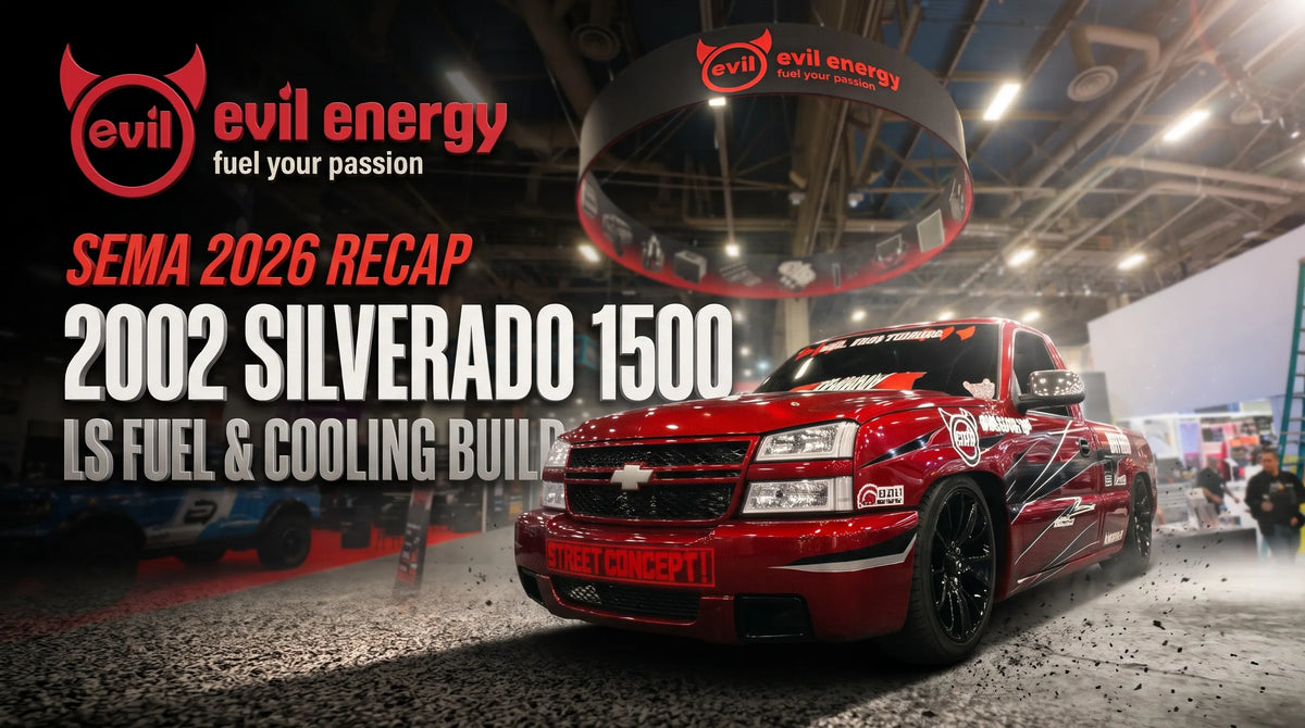
SEMA Show 2026 ran November 3-6 at the Las Vegas Convention Center, and for EVIL ENERGY it marked ten years. We started in 2016 with a single V-band clamp. This year, the sign over Central Hall Booth #24313 read "10 Years Proven. One-Stop Fuel & Air Parts Solution," and the whole booth was organized around three systems: fuel, intake and cooling.
The star of the booth was our red 2002 Chevrolet Silverado 1500 Regular Cab, still powered by its original 4.8L LS V8. This recap walks through the finished truck one system at a time. For each system, it explains what we installed, why each part is there, how the systems depend on each other, and what to check when you do the same work on your own GMT800 or LS swap.

The Base Truck: 2002 Silverado 1500 with the 4.8L LR4
We chose a truck that thousands of owners still drive every day. A GMT800 Silverado is old enough that its factory fuel, cooling and fluid hardware is due for attention. It is also common enough that every lesson from this build carries over to real driveway projects.
| Spec | Featured build |
|---|---|
| Vehicle | 2002 Chevrolet Silverado 1500 (1/2 ton), Regular Cab, 2-door pickup |
| Platform | GMT800 |
| Engine | 4.8L (4,800 cc / about 293 ci) LR4 V8, iron block, LS family |
| Fuel / injection | Gasoline, multipoint fuel injection (MPFI) |
| Drivetrain | 4x2 |
| Transmission | 4L60E |
| GVWR | Class 2E: 6,001-7,000 lb |
| Assembly plant | Fort Wayne Assembly, Indiana, USA |

Why We Built It as One System
A 20-year-old truck does not need random bolt-ons. It needs its supporting systems brought up together, because each one loads the others:
- Airflow and fuel. More airflow through a larger throttle body means the fuel system has to keep rail pressure steady at higher demand.
- Load and heat. Working the truck harder puts more heat into the coolant, the engine oil, the 4L60E and the power steering fluid.
- Cooling hardware and airflow. Electric fans change how air moves across the radiator and every cooler stacked in front of it.
- Crankcase ventilation. Crankcase vapors end up in the intake, so ventilation affects the intake side too.
Planning the systems together avoids the classic trap: fixing one bottleneck only to expose the next one.

Fuel System: Fuel Cell, External EFI Pump and Return-Style Regulation
An aging factory fuel setup is the first weak point on a hard-working LS truck, so the build started at the back of the truck. The factory tank and in-tank pump module came out. A complete fuel cell system replaced them.

From In-Tank Module to External Pump
The factory GMT800 design hides the pump, strainer and level sender inside the tank. Our 15-gallon aluminum fuel cell kit moves the pump outside the tank, and the truck is fed by a 405LPH external EFI fuel pump. Once the pump is external, pump placement, filter staging, line routing and venting stop being a sealed factory module. They become engineering decisions. Get those decisions right and you have a fuel system you can service, inspect and grow into.
- Pump placement. Inline pumps are much better at pushing fuel than pulling it. Mount the pump low and close to the cell outlet so it is gravity-fed and never has to lift fuel a long way on the suction side.
- Filter staging. The kit pairs a coarse 100-micron filter with finer 30- and 10-micron elements. The coarse filter goes before the pump, so debris never reaches the pump without restricting its inlet. The finer filtration goes after the pump, where it protects the injectors, which have the tightest tolerances in the system.
- Return-style regulation. A fuel pressure regulator holds rail pressure, and the fuel the engine does not use flows back to the cell through a dedicated return line. Constant circulation keeps pressure stable as demand changes. It also stops fuel from sitting and heat-soaking in the rail.
- Venting. A vent check valve on top of the cell lets air in as fuel is drawn down, so the cell never pulls a vacuum that would starve the pump, while still controlling spillage.
- Keeping the fuel gauge. The factory pump connector carries pump power and ground plus the fuel level sender's signal and reference circuits. Mapping those circuits correctly is what keeps the dash fuel gauge reading with an aftermarket cell.

PTFE Fuel Line: Why Not Rubber?
Fuel is carried in braided PTFE hose from our PTFE LS swap EFI fuel line kit and PTFE fuel line kit. PTFE wins for three reasons:
- Ethanol and E85 compatibility. The PTFE liner is chemically inert to gasoline and ethanol blends, so it does not swell, harden or shed material the way some rubber compounds can over time.
- Low permeation. Very little vapor escapes through a PTFE wall, which means less fuel smell in the garage and cab.
- Pressure and abrasion protection. The braided jacket carries EFI pressure and protects the liner wherever the hose runs along the chassis.
The catch is that PTFE hose must use PTFE-specific hose ends. These ends seal with an olive (ferrule) that clamps the liner. Standard rubber-hose AN ends are a different design, and mixing the two is one of the most common sources of fuel leaks we see.

AN Fittings and Quick Disconnects
AN fittings seal on a 37-degree flare, metal to metal. Clean, undamaged flares and correct torque make the seal. Thread tape or sealant has no place on the flare itself.
Where AN hose meets factory-style connections, adapters do the translation. On this truck, 8AN to 3/8 in SAE quick-disconnect EFI fittings let the AN plumbing click onto factory-style 3/8 in quick-connect fuel fittings. That means no cutting or modifying factory-style fuel connections.
Fuel System Install Checks
- Route safely. Keep lines away from exhaust heat, moving suspension and sharp edges, and use proper clamps along the chassis.
- Prime before cranking. Cycle the key on and off several times so the pump fills the lines, filters and rail before the engine cranks. Then check rail pressure with a gauge and set the regulator.
- Leak test under pressure. With the system pressurized and the engine off, inspect every hose end, adapter and filter housing. Check again after the first heat cycle, when fittings have expanded and cooled once.
- Service the filters. Clean or replace the pre-pump filter after initial startup, because a new fuel cell and new lines can shed debris.

Engine Cooling: Radiator, Electric Fans and Steam Venting
The engine cooling circuit on the Silverado was rebuilt as one system:
- Radiator. A direct-fit 3-row 56mm aluminum radiator for the Silverado.
- Fans. Twin 16-inch fans from our 12V electric radiator cooling fan kit.
- Reservoir. A new coolant reservoir overflow tank.
- Steam venting. An LS coolant crossover steam vent kit.

Electric Fans vs. the Mechanical Fan
An engine-driven fan's speed is tied to engine rpm. It moves the least air at idle in traffic, which is when a truck needs airflow the most. It moves the most air at highway speed, when ram air through the grille is already doing the work. It also takes power off the crank the whole time.
Electric fans remove that parasitic drag and run on demand, based on temperature, so airflow is there at low vehicle speed. There is a system benefit too: the radiator and every cooler stacked with it see controlled airflow whether the truck is moving or not.
Wire the fans through a fused relay and a temperature controller rather than straight to a switched circuit. Confirm airflow direction before the first drive, so the fans pull or push in the same direction as ram air.
A Thicker Aluminum Core
A 3-row aluminum core holds more coolant and gives more tube surface for heat transfer than a thinner stock-style core. Our Silverado radiator also includes built-in transmission and engine oil cooler provisions that match the factory design, so the factory plumbing layout is preserved. The reservoir and cap let coolant expand and return as it heats and cools, without pulling air into the system.

LS Steam Vent Kit: Purging Air from the Heads
LS cylinder heads have steam ports at the front and rear of each head. Their job is to let trapped air and steam escape from the highest points of the coolant passages. If those pockets stay trapped, they insulate parts of the combustion chamber area from coolant. The result is localized hot spots, even when the dash gauge looks normal.
The steam vent kit ties the front and rear ports of both heads into a single CNC-machined manifold with stainless lines. That gives trapped steam a dedicated path out, improves coolant circulation through the heads and helps keep cylinder temperatures even.
Coolant Fill and Bleed Checks
- Fill slowly. Fill with the heater set to hot so the heater core circuit fills too.
- Purge the air. Let the engine reach operating temperature with the cap off or the reservoir open, so air purges through the steam vent path. Top up as the level drops.
- Confirm the fans. Make sure the electric fans switch on and off as the engine warms and cools.
- Recheck cold. Check the coolant level again after a full cool-down, and check hose clamps and steam vent fittings for seepage.
Engine Oil and Transmission Cooling: Separate Circuits
Heat is hard on a 4L60E, and it is just as hard on engine oil in a truck that tows or idles in traffic. We gave the engine oil and the transmission their own external stacked-plate coolers, each with its own fan. On the truck, the cooler on the left is the transmission cooler and the cooler on the right is the engine oil cooler. The parts come from our transmission and engine oil cooler kit with bracket and our oil cooling solution kit with bracket.
Why separate circuits?
- Different fluids, different jobs. Engine oil and automatic transmission fluid work in different temperature windows. Overheated ATF loses its friction properties and oxidizes, which shortens clutch and seal life.
- No cross heat soak. Dedicated coolers keep each fluid from picking up the other's heat.
- Independent sizing and routing. Each circuit is plumbed to suit its own flow and pressure.
- Fans for slow, heavy work. Cooler fans keep air moving at low vehicle speed, exactly when a working truck builds the most heat.
The plumbing follows the fluid:
- Transmission circuit. A PTFE line runs between the transmission cooler and the 4L60E. At the case, 6AN to 1/4 NPSM transmission cooler adapter fittings convert the factory ports to AN. NPSM is a straight pipe thread that seals with a gasket instead of tapered threads. These adapters seal on a 37-degree flare on the AN side and a copper gasket on the NPSM side.
- Engine oil circuit. A PTFE line runs from the engine oil cooler straight to the engine, sized generously to keep restriction low.
- Hose ends. Six 90-degree PTFE hose ends handle the tight turns: two at the engine cooler, two at the cooler adapter and two at the catch can. Ninety-degree ends keep hoses clear of hot or sharp edges without tight bends that would kink or restrict flow.
Fluid Checks After Adding Coolers
- Re-check fluid levels. External coolers and lines add fluid capacity. Re-check engine oil after the first run.
- Check the transmission correctly. Check transmission fluid using the correct procedure for the 4L60E at operating temperature.
- Inspect for leaks. Look over every adapter and hose end with the system hot and under load.
Power Steering Cooling
Power steering is the system most builders forget. The pump adds heat every time the wheel turns, especially during slow maneuvering, and hot fluid foams and wears seals faster. On the Silverado, power steering fluid gets its own stacked-plate cooler with a dedicated 8-inch electric fan. That way the circuit gets airflow even when the truck is barely moving. The cooler sits on the low-pressure return side, so the fluid is cooled before it goes back to the reservoir.
Connecting AN hose to factory power steering hardware takes the right adapters:
- Metric O-ring ports. 6AN to metric O-ring power steering adapters in M16x1.5 and M18x1.5 suit metric O-ring ports. These ports seal on the O-ring, not on the threads, so the O-ring must be seated, lubricated and undamaged.
- Inverted flare connections. 6AN to inverted flare adapters in 5/8-18 and 11/16-18 tie AN hose into inverted-flare connections, a style common on GM factory hard lines.
After installation, bleed the air out. With the front wheels off the ground and the engine off, turn the wheel slowly lock to lock several times. Top up the fluid, then repeat with the engine running until the fluid is free of bubbles.
Intake, Ignition and Bottom End


Throttle Body
The LS breathes through our 102mm LS throttle body. It is a mechanical (cable) unit with an idle air control (IAC) motor included. A larger throttle bore raises the engine's airflow ceiling at high load. That airflow only helps when the fuel system can keep up, which is why the fuel side was rebuilt first.
Match throttle body size to the intake manifold opening, and note that this unit does not include a throttle position sensor (TPS), so plan to transfer or source one. After the swap, check idle quality and confirm the tune.
Ignition Coils
Fresh ignition coils went on as well. On an LS that is more than 20 years old, weak coils can cause misfires under load. Those misfires are easily mistaken for a fuel delivery problem, so new coils remove one variable when you diagnose the rest of the system.
Harmonic Balancer Bolt
Down low, a 42CrMo harmonic balancer bolt for LS Gen III/IV engines secures the balancer. The factory LS crank bolt is a torque-to-yield design intended for one-time use. Any time the balancer comes off for front-end work, a new bolt should go back in, torqued to spec.
Crankcase Ventilation: Oil Catch Can and PCV

Every engine has blow-by: combustion gases that slip past the piston rings into the crankcase. The positive crankcase ventilation (PCV) system pulls those gases back into the intake to be burned, but the gases carry oil mist. Over time, that oil coats the intake tract and throttle body and builds deposits.
Our 1.2L 10AN baffled oil catch can sits between the PCV source and the intake manifold. Internal baffles force the vapor to change direction, so oil droplets drop out before the gases return to the intake. A bottom drain valve makes emptying it a quick routine job. The can uses PTFE hose ends at its ports, which ties it into the same plumbing standard as the rest of the truck.
Check and drain the can regularly, especially in cold weather, when moisture collects alongside the oil.
At the Booth: Fuel, Intake and Cooling Together

The rest of the booth followed the same system-first idea. Product walls grouped EFI fuel delivery, carbureted fuel systems and powertrain thermal management, so visitors could trace a part from the tank to the rail or from the radiator to each cooler. The red Silverado sat right beside them with the hood up, so builders could see how those parts fit together in a real truck. Our crew spent the show walking visitors through the fuel routing, cooler plumbing and fittings.

Build Parts Summary
| System | Installed parts |
|---|---|
| Fuel | 15-gallon fuel cell kit, 405LPH external EFI pump, PTFE fuel lines, 8AN to 3/8 in quick-disconnect EFI fittings |
| Engine cooling | 3-row 56mm aluminum radiator, twin 16-inch electric fans, coolant reservoir, LS steam vent kit |
| Oil and transmission | Separate engine oil and transmission stacked-plate coolers with fans, PTFE lines, 6AN to 1/4 NPSM 4L60E adapters, 90-degree PTFE hose ends |
| Power steering | Stacked-plate power steering cooler, 8-inch electric fan, 6AN to M16/M18 metric O-ring adapters, 6AN to inverted flare adapters |
| Intake, ignition and engine | 102mm throttle body, ignition coils, 42CrMo harmonic balancer bolt |
| Crankcase ventilation | 1.2L 10AN baffled oil catch can |
FAQ
Q: What engine is in the EVIL ENERGY SEMA 2026 Silverado?
A: The red Silverado keeps its original 4.8L LR4 V8. It is an iron-block member of the GM LS family with multipoint fuel injection, in a 2002 Silverado 1500 Regular Cab 4x2.
Q: Why use a fuel cell with an external pump instead of the factory tank?
A: An external pump makes the system serviceable and lets you choose pump placement, filter staging and return routing yourself. A coarse filter before the pump and finer filters after it protect both the pump and the injectors. The return line keeps rail pressure steady.
Q: Why use separate engine oil, transmission and power steering coolers?
A: Each fluid works in its own temperature window, and each one degrades when overheated. Separate coolers stop the fluids from heat-soaking each other, and each circuit can be sized and plumbed on its own.
Q: Is PTFE fuel line better than rubber for E85?
A: PTFE-lined hose is chemically resistant to ethanol blends, including E85, and has very low vapor permeation. Always pair it with PTFE-specific hose ends.
Q: What does an LS steam vent kit do?
A: It connects the steam ports at the front and rear of both LS cylinder heads, giving trapped air and steam a path out of the coolant passages. That helps prevent hot spots around the combustion chambers and makes bleeding the cooling system easier.
Q: Are electric fans better than the factory mechanical fan?
A: Electric fans remove belt-driven drag and supply airflow based on temperature, not engine rpm, so they help most at idle and low speed. Wire them through a fused relay and controller.
Q: Do I need a catch can on an LS truck?
A: A catch can is not required, but it is a smart upgrade. It traps oil mist from the PCV system before it reaches the intake, which helps reduce deposits. Drain it as part of regular maintenance.
Build Your Own System, Not Just a Parts List
Thank you to everyone who stopped by Booth #24313 and talked fuel lines, fittings and cooling with our crew. If the red Silverado gave you ideas for your own truck, start with the system that limits you most. Shop our fuel system parts or cooling system parts, or read our SEMA Show 2026 Day 1 recap. Not sure what fits your build? Email support@ievilenergy.com or call +1 (866) 850-9888, Monday to Friday, 9:00 AM to 6:00 PM ET, and we'll help you plan it from the tank to the rail.


